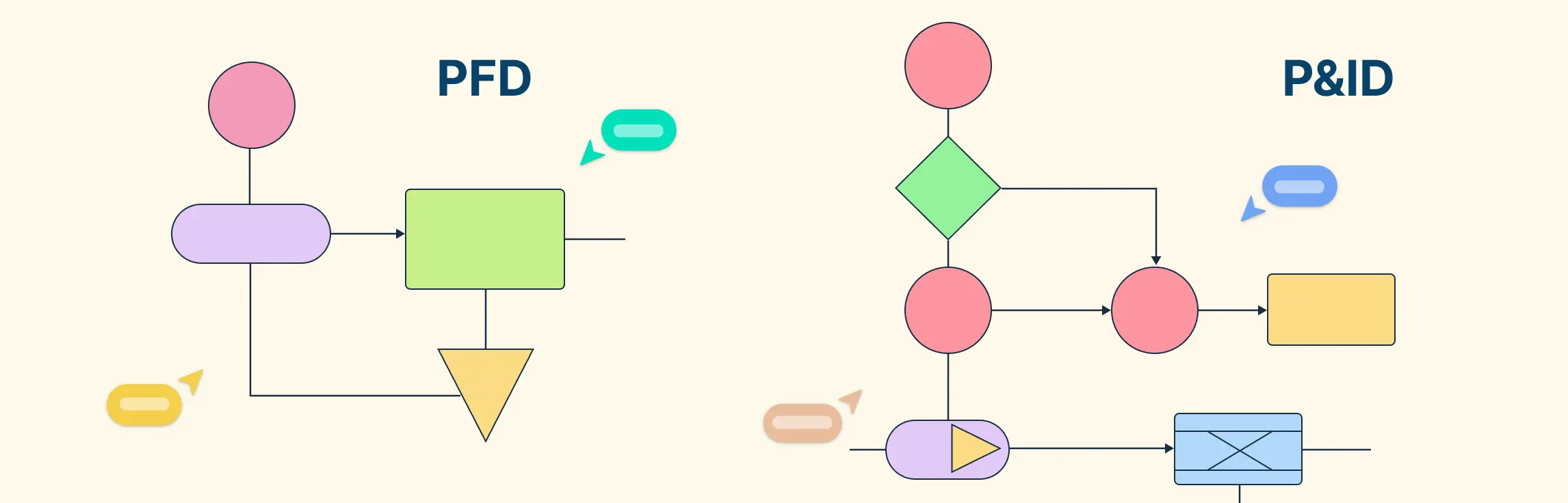
A Process Flow Diagram (PFD) is a document created during the early stages of process design to show the major equipment required, how different units are connected, and the direction of material flow throughout a process. A Piping and Instrumentation Diagram (P&ID) is a more detailed engineering document that includes piping systems, valves, instruments, control loops, and process control information required for operation and maintenance.
Understanding PFD vs P&ID is essential for professionals working in pharmaceutical manufacturing, chemical processing, utilities, and engineering projects. Although both documents describe the same process, they serve different purposes and contain different levels of detail.
A PFD provides a simplified overview of the process that can be understood at a glance, making it useful during process development and project planning. In contrast, a P&ID provides detailed information about equipment connections, instrumentation, safety systems, and process controls used during construction, qualification, operation, and maintenance.
In the pharmaceutical industry, both documents play a critical role in facility design, GMP compliance, validation activities, troubleshooting, and regulatory inspections. Engineers, validation professionals, maintenance teams, and operators rely on these drawings to understand how pharmaceutical systems function and how critical process parameters are controlled.
This comprehensive guide explains PFD vs P&ID, including their purpose, components, symbols, differences, applications, benefits, and importance in pharmaceutical engineering.
What is a Process Flow Diagram (PFD)?
A Process Flow Diagram (PFD) is a simplified representation of a manufacturing process. It shows the major process equipment and the overall flow of materials through the system.
Typical elements in a PFD include:
Reactors
Tanks
Mixers
Heat exchangers
Pumps
Main process streams
Flow directions
A PFD does not usually show detailed instrumentation, valve types, line numbers, control loops, or utility connections. Its primary purpose is to communicate how the process works at a high level.
What Are the Key Components of a PFD?
A Process Flow Diagram (PFD) provides a high-level overview of a process and shows how materials move through a system. It is designed to help engineers understand the process flow, major equipment, and operating conditions without including excessive detail. Every PFD should contain the following key components.
1. Process Flow Lines
Process flow lines are one of the most important components of a PFD. These lines show how materials move from one piece of equipment to another and indicate the direction of flow throughout the process.
Process flow lines often include information such as:
- Flow rate
- Temperature
- Pressure
- Stream composition
- Mass balance data
- Energy balance data
This information helps engineers analyze process performance and verify design requirements.
2. Main Equipment
A PFD includes all major equipment involved in the manufacturing process. The equipment is represented using standard symbols and is usually identified by a unique equipment number.
Examples of main equipment include:
- Reactors
- Storage tanks
- Mixing vessels
- Pumps
- Heat exchangers
- Filters
- Distillation columns
- Dryers
The purpose of showing main equipment is to provide a clear understanding of the process sequence and equipment interaction.
3. Process Streams
Process streams represent the materials flowing through the system. These streams may include raw materials, intermediates, finished products, solvents, water, steam, and other process fluids.
Each stream is typically assigned a stream number and may include operating data for process evaluation.
4. Flow Direction
Flow direction is indicated using arrows on process lines. This allows engineers and operators to quickly understand the movement of materials throughout the process and identify the order of operations.
5. Operating Conditions
Many PFDs include important operating parameters that describe process conditions.
Examples include:
- Temperature
- Pressure
- Flow rate
- Density
- Composition
These values help engineers perform process calculations and optimize system performance.
6. Utility Streams
Utility systems that support the process may also be shown on a PFD.
Examples include:
- Steam
- Cooling water
- Chilled water
- Compressed air
- Nitrogen
Utility streams help users understand how support systems interact with the manufacturing process.
7. Equipment Identification Tags
Every major equipment item is assigned a unique tag number for easy identification.
Examples:
- P-101 (Pump)
- V-101 (Vessel)
- R-101 (Reactor)
- HX-101 (Heat Exchanger)
These tags are used throughout engineering, maintenance, validation, and operational documentation.
Key Takeaway
The key components of a PFD include process flow lines, main equipment, process streams, flow direction, operating conditions, utility streams, and equipment identification tags. Together, these elements provide a clear overview of the process and help engineers understand how a manufacturing system operates before moving to more detailed documents such as P&IDs.
What is a Piping and Instrumentation Diagram (P&ID)?
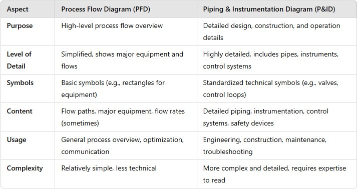
A P&ID (Piping and Instrumentation Diagram) is a detailed engineering drawing that expands on the PFD. It includes the piping network, instruments, valves, control systems, alarms, interlocks, utility connections, and other information required to build, operate, maintain, qualify, and troubleshoot the system.
Typical elements in a P&ID include:
Equipment tags (V-101, P-101, HX-101, etc.)
Pipe line numbers
Pipe sizes and specifications
Valve types and positions
Flow, pressure, temperature, and level instruments
Control loops and transmitters
Utility connections
Drain, vent, and sampling points
Safety devices and relief systems
In the PFD vs P&ID comparison, the P&ID is the document that operators, maintenance technicians, validation engineers, and inspectors depend on for detailed system understanding.
What Should Be Included in a P&ID?
A Piping and Instrumentation Diagram (P&ID) is far more detailed than a Process Flow Diagram (PFD). While a PFD provides a high-level overview of a process, a P&ID contains detailed engineering information required for system design, construction, operation, maintenance, troubleshooting, validation, and regulatory compliance.
A P&ID provides a complete picture of how a process operates by showing equipment, piping systems, valves, instruments, control loops, and utility connections. The following elements should typically be included in a P&ID.
1. Piping Information
Piping details are one of the most important components of a P&ID. Every process line should contain information such as:
- Pipe size
- Line number
- Pipe material
- Insulation details
- Flow direction
- Service description
These details help engineers and maintenance teams identify and manage process piping systems accurately.
2. Utility Lines, Drains, and Vents
A P&ID should clearly identify utility systems that support the manufacturing process.
Examples include:
- Steam lines
- Compressed air lines
- Nitrogen lines
- Cooling water lines
- Chilled water systems
Drains and vents are also shown to help operators understand system cleaning, maintenance, and pressure relief arrangements.
3. Isolation and Shut-Off Valves
Valves play a critical role in controlling fluid flow throughout the process. A P&ID includes the location and type of valves used in the system.
Common examples include:
- Ball valves
- Gate valves
- Butterfly valves
- Diaphragm valves
- Control valves
Isolation and shut-off valves allow equipment to be safely maintained and operated without affecting the entire process.
4. Instrumentation and Signal Connections
Instrumentation is a major feature that distinguishes a P&ID from a PFD. A P&ID identifies all instruments used to monitor and control process conditions.
Examples include:
- Pressure indicators (PI)
- Pressure transmitters (PT)
- Temperature indicators (TI)
- Temperature transmitters (TT)
- Flow transmitters (FT)
- Level transmitters (LT)
Signal connections between instruments and control systems are also shown to illustrate how process parameters are monitored and controlled.
5. Process Flow and Stream Information
Like a PFD, a P&ID includes process flow lines and stream information. These lines help explain:
- Material flow paths
- Mass balance information
- Energy balance information
- Flow rates
- Temperatures
- Pressures
- Stream composition
This information helps engineers understand process performance and system operation.
6. Control Loops
Control loops are an essential part of every P&ID. They show how process variables are automatically controlled to maintain desired operating conditions.
Examples include:
- Temperature control loops
- Pressure control loops
- Flow control loops
- Level control loops
Control loops help ensure product quality, process consistency, and operational safety.
7. Equipment Identification
A P&ID includes a basic equipment list that identifies major process equipment.
Examples include:
- Pumps
- Heat exchangers
- Storage tanks
- Reactors
- Filters
- Compressors
- Mixing vessels
Each equipment item is assigned a unique identification tag for easy reference throughout engineering and maintenance documentation.
8. Safety Devices
Many P&IDs also include safety-related equipment such as:
- Pressure relief valves
- Safety valves
- Rupture discs
- Emergency shutdown systems
- Alarm systems
These components help protect personnel, equipment, and product quality during operation.
Key Takeaway
A P&ID contains detailed information about piping systems, utility lines, valves, instrumentation, process streams, control loops, safety devices, and equipment. Because of this high level of detail, P&IDs are essential for engineering design, pharmaceutical validation, maintenance activities, troubleshooting, and regulatory compliance. Unlike a PFD, a P&ID provides the complete technical information needed to understand, operate, and maintain a process safely and efficiently.
PFD vs P&ID: Quick Comparison
Feature | PFD | P&ID |
|---|---|---|
Purpose | High-level process overview | Detailed engineering and control document |
Process equipment | Shown | Shown with tags |
Piping details | Minimal | Extensive |
Valve types | Usually omitted | Fully identified |
Instruments | Limited or omitted | Comprehensive |
Control loops | Not shown | Shown |
Line numbers | Rarely shown | Typically shown |
Utility connections | Limited | Detailed |
Construction use | Limited | Extensive |
Validation use | Reference level | Critical reference document |
Maintenance use | Low | High |
Regulatory review value | Background understanding | Detailed system verification |
Why the Difference Matters in Pharma
Pharmaceutical facilities are highly regulated. Teams need both documents, but for different reasons:
Activity | Primary Document |
|---|---|
Conceptual process design | PFD |
Production planning | PFD |
Detailed engineering design | P&ID |
Construction and installation | P&ID |
Equipment qualification (IQ/OQ/PQ) | P&ID |
Maintenance troubleshooting | P&ID |
HAZOP and safety reviews | P&ID |
Operator training overview | PFD (often with P&ID support) |
In practice, most validation activities depend heavily on the P&ID, not just the PFD.
Typical PFD Content
Consider a simplified purified water generation system.
A PFD may show:
Feed water tank
Pre-treatment unit
Reverse osmosis unit
EDI unit
Purified water storage tank
Distribution pump
Return loop
Arrows indicate the general flow direction. The PFD communicates the overall process sequence but does not show every valve, transmitter, or line number.
Typical P&ID Content
The corresponding P&ID would add:
Equipment tags (TK-101, P-101, RO-101, etc.)
Pipe line numbers and sizes
Isolation valves
Diaphragm valves
Pressure indicators
Conductivity transmitters
Temperature sensors
Sampling points
Drain valves
Control loops
Utility tie-ins
Alarm and interlock connections
This level of detail is what makes the PFD vs P&ID distinction so important in pharmaceutical engineering.
PFD vs P&ID in Validation and Qualification
Design Qualification (DQ)
The PFD helps reviewers understand the intended process flow, while the P&ID verifies that detailed design elements support user requirements.
Installation Qualification (IQ)
The P&ID is used to confirm that equipment, piping, valves, and instruments have been installed according to approved design documents.
Operational Qualification (OQ)
OQ protocols rely on P&IDs to identify control loops, alarms, interlocks, and operating ranges that must be tested.
Performance Qualification (PQ)
P&IDs help determine sampling locations, critical monitoring points, and system boundaries used during routine performance verification.
For this reason, in the PFD vs P&ID discussion, the P&ID is generally considered the more critical document for qualification and validation execution.
Regulatory Perspective
Regulatory inspectors may review engineering documentation to understand system design and control. A PFD helps provide process context, but inspectors often rely on P&IDs to verify:
Critical control points
Utility connections
Sampling arrangements
Instrumentation layout
Alarm and interlock implementation
Equipment identification consistency
Accurate and current P&IDs strengthen GMP compliance and inspection readiness.
Common PFD Symbols
Although symbol standards vary by organization, common PFD symbols represent:
Symbol Type | Meaning |
|---|---|
Rectangle or vessel outline | Tank or vessel |
Circle with triangle | Pump |
Heat exchanger shape | Heat exchanger |
Arrowed line | Process stream |
In a PFD, the emphasis is on process flow, not detailed control instrumentation.
Common P&ID Symbols
P&IDs include a much larger symbol set, such as:
Symbol Type | Meaning |
|---|---|
Control valve | Automatic flow or pressure control |
Pressure transmitter (PT) | Pressure measurement signal |
Temperature indicator (TI) | Local temperature display |
Flow transmitter (FT) | Flow measurement signal |
Level transmitter (LT) | Level measurement signal |
Signal line (dashed) | Control or communication signal |
Learning these symbols is a major step toward mastering PFD vs P&ID interpretation.
Industry Examples
Purified Water System
PFD: Shows the sequence: pretreatment → RO → EDI → storage → distribution.
P&ID: Shows every pump, valve, conductivity transmitter, temperature sensor, sampling point, and return line.
Clean Steam Generation
PFD: Shows feed water entering the generator and clean steam leaving the system.
P&ID: Adds pressure control valves, condensate drains, steam traps, transmitters, alarms, and isolation points.
HVAC System
PFD: May show air handling units and major airflow paths.
P&ID: Includes dampers, differential pressure transmitters, temperature sensors, control valves, and alarm connections.
When Should You Use a PFD?
Choose a PFD when you need:
A high-level process overview
Early design discussions
Process sequence communication
Management presentations
Training on overall process flow
Feasibility studies
When Should You Use a P&ID?
Choose a P&ID when you need:
Detailed engineering design
Construction and installation reference
Instrumentation and control information
Maintenance troubleshooting
Validation and qualification support
HAZOP and safety review documentation
Regulatory inspection readiness
Frequent Beginner Mistakes
Assuming a PFD contains all valves and instruments. It usually does not.
Using a PFD for maintenance troubleshooting. Maintenance teams generally need the P&ID.
Treating a P&ID as a simplified flowchart. A P&ID is a detailed engineering document.
Ignoring revision control. Outdated P&IDs can create qualification and operational risks.
Confusing instrument tags with equipment tags. Learn the plant tagging convention before interpreting the drawing.
Best Practices for Managing PFDs and P&IDs
Maintain strict revision control.
Update drawings through formal change control.
Use standardized symbol libraries.
Ensure tag consistency across drawings and asset registers.
Train operators and maintenance personnel on document interpretation.
Link P&IDs to qualification, calibration, and maintenance records.
Archive superseded versions properly to preserve traceability.
Conclusion
Understanding PFD vs P&ID is essential for anyone working in pharmaceutical manufacturing, process engineering, validation, or industrial operations. Although both documents describe the same process, they serve different purposes and provide different levels of detail.
A Process Flow Diagram (PFD) offers a simplified overview of the process, showing major equipment, material flow, and operating conditions. In contrast, a Piping and Instrumentation Diagram (P&ID) provides detailed information about piping systems, valves, instrumentation, control loops, utility connections, and safety devices required for day-to-day operations.
In the pharmaceutical industry, both PFDs and P&IDs play a critical role in facility design, equipment qualification, process validation, maintenance planning, troubleshooting, and regulatory compliance. While the PFD helps stakeholders understand the overall process, the P&ID serves as the primary engineering document used for construction, operation, and system control.
By understanding the differences between PFD vs P&ID, pharmaceutical professionals can improve process understanding, enhance operational efficiency, support GMP compliance, and contribute to the safe and reliable manufacture of high-quality pharmaceutical products.
Frequently Asked Questions (FAQs)
Q1. What is the main difference between PFD and P&ID?
The main difference between PFD vs P&ID is the level of detail. A Process Flow Diagram (PFD) provides a high-level overview of the process, while a Piping and Instrumentation Diagram (P&ID) contains detailed information about piping, valves, instruments, control loops, and utility systems.
Q2. What does PFD stand for?
PFD stands for Process Flow Diagram. It is used to show the major equipment, material flow, and operating conditions within a process.
Q3. What does P&ID stand for?
P&ID stands for Piping and Instrumentation Diagram. It is a detailed engineering drawing that shows piping systems, instrumentation, valves, equipment, and control systems.
Q4. Why is P&ID more detailed than a PFD?
A P&ID is designed for engineering, construction, operation, maintenance, and troubleshooting purposes. Therefore, it contains detailed information such as pipe sizes, line numbers, instrumentation, control loops, utility connections, and safety systems that are not typically included in a PFD.
Q5. Is a PFD created before a P&ID?
Yes. During the design process, a PFD is usually developed first to show the overall process flow. Once the process design is finalized, engineers create a P&ID with detailed engineering information.
Q6. Why are PFDs and P&IDs important in the pharmaceutical industry?
PFDs and P&IDs are essential because they help engineers understand process design, support validation activities, improve troubleshooting, ensure GMP compliance, and provide documentation required during regulatory inspections.
Q7. Who uses PFDs and P&IDs?
PFDs and P&IDs are commonly used by:
- Process Engineers
- Pharmaceutical Engineers
- Validation Engineers
- Production Personnel
- Maintenance Teams
- Quality Assurance Professionals
- Regulatory Inspectors
Q8. Are P&IDs required for pharmaceutical validation?
Yes. P&IDs are important documents during Design Qualification (DQ), Installation Qualification (IQ), Operational Qualification (OQ), and Performance Qualification (PQ) because they provide detailed information about equipment, piping, instrumentation, and control systems.