Pump sizing calculation is an important process engineering activity used to select a pump that can deliver the required liquid flow rate at the required pressure and total head. A properly sized pump ensures reliable transfer of water, solvents, chemicals, purified water, process solutions, and other liquids throughout a pharmaceutical manufacturing plant.
Pump selection is not simply a matter of choosing a pump based on flow rate. The engineer must consider flow rate, static head, friction losses, equipment pressure, fluid properties, pump efficiency, motor power, NPSH, operating temperature, and system conditions.
In pharmaceutical plants, pumps are commonly used for:
- Raw material transfer
- Solvent transfer
- Reactor charging
- Purified water circulation
- WFI circulation
- CIP systems
- Cooling water circulation
- Product transfer
- Boiler feedwater
- Wastewater transfer
- Chemical dosing
- Filtration systems
An incorrect pump selection can cause insufficient flow, excessive energy consumption, cavitation, mechanical problems, high maintenance costs, and process interruptions.
This guide explains the pump sizing calculation method step by step and includes practical numerical examples for process engineers, pharmaceutical engineers, chemical engineering students, and plant professionals.
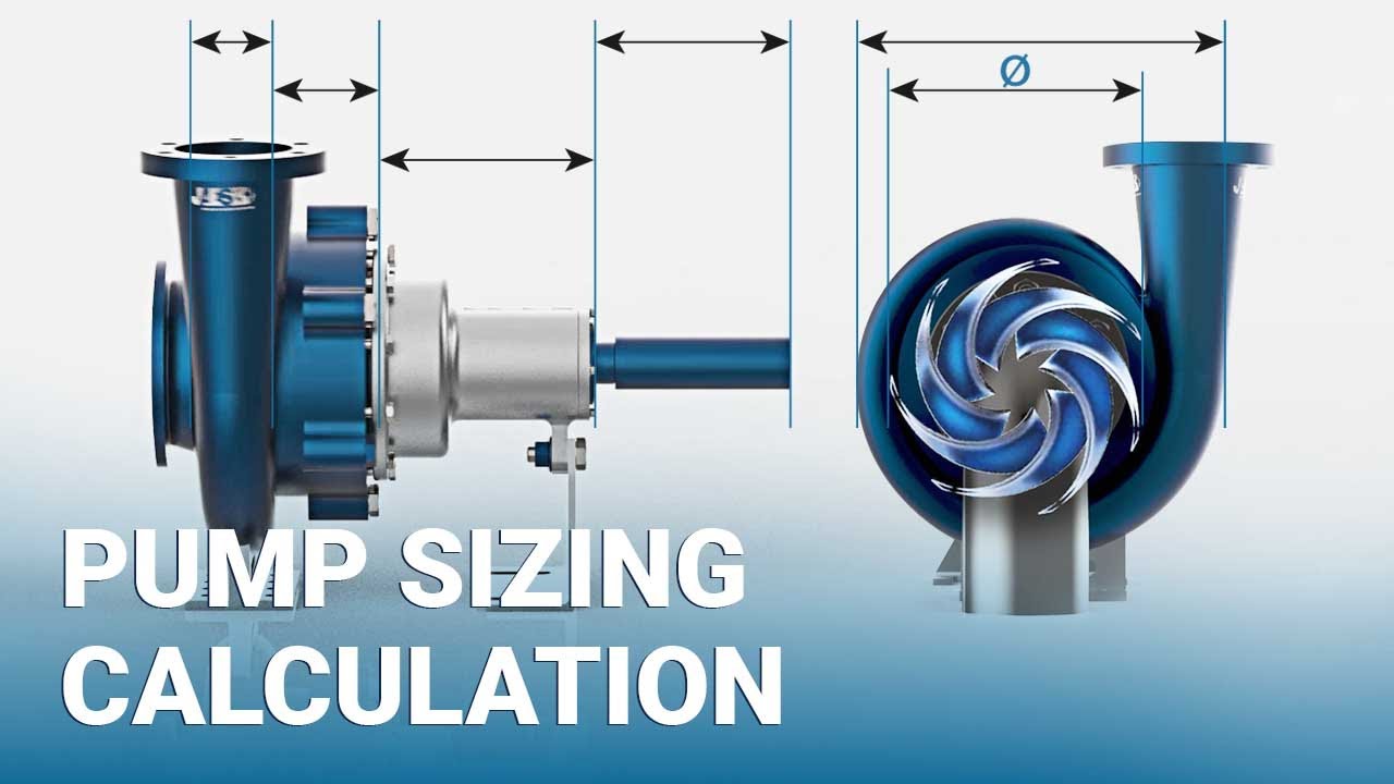
What Is Pump Sizing?
Pump sizing is the engineering process of determining the required pump capacity and selecting a suitable pump based on the process requirements.
The main parameters required for pump selection are:
- Required flow rate
- Static head
- Pressure head
- Friction head
- Total Dynamic Head (TDH)
- Fluid density
- Fluid viscosity
- Pump efficiency
- Motor power
- NPSH available
- NPSH required
- Operating temperature
- Pump material of construction
The selected pump should operate close to its Best Efficiency Point (BEP) whenever practical.
Why Is Pump Sizing Important?
Correct pump sizing provides:
- Required process flow
- Stable operation
- Lower energy consumption
- Reduced cavitation risk
- Better equipment reliability
- Longer pump life
- Lower maintenance cost
- Improved process control
An oversized pump may consume unnecessary power and operate away from its preferred operating region. An undersized pump may fail to achieve the required flow or pressure.
Therefore, accurate pump sizing calculation is important during both new plant design and modification of existing systems.
Basic Pump Sizing Calculation Parameters
Before starting the calculation, collect the following information.
| Parameter | Typical Unit |
|---|---|
| Flow Rate | m³/hr |
| Pressure | bar |
| Head | m |
| Density | kg/m³ |
| Viscosity | cP |
| Temperature | °C |
| Efficiency | % |
| Power | kW |
| NPSH | m |
| Pipe Diameter | mm |
| Pipe Length | m |
Step 1: Calculate Required Flow Rate
Flow rate is normally obtained from the process requirement.
For a batch transfer:
[Q=\frac{V}{t}]
Where:
- Q = Flow rate
- V = Liquid volume
- t = Transfer time
If volume is in m³ and time is in hours, the resulting flow rate is m³/hr.
Example 1: Flow Rate Calculation
A pharmaceutical reactor contains 12 m³ of liquid.
The required transfer time is 1.5 hours.
Calculate the required pump flow rate.
Solution
[Q=\frac{V}{t}]
[Q=\frac{12}{1.5}]
[Q=8\ m^3/hr]
Therefore:
Required Flow Rate = 8 m³/hr
If a design margin of 10% is applied:
[Q_{design}=8\times1.10]
[Q_{design}=8.8\ m^3/hr]
A pump with an appropriate operating point around 8.8 m³/hr can therefore be considered, subject to the complete hydraulic calculation.
Step 2: Calculate Static Head
Static head is the vertical elevation difference between the liquid source and destination.
[H_{static}=Z_2-Z_1]
Where:
- Z₂ = Destination elevation
- Z₁ = Source elevation
Example 2: Static Head
A storage tank liquid level is at an elevation of 2 m.
The receiving reactor inlet is at 18 m.
Calculate static head.
[H_{static}=18-2]
[H_{static}=16\ m]
Static Head = 16 m
Step 3: Pressure Head Calculation
When the suction and discharge vessels operate at different pressures, the pressure difference must be converted into head.
The pressure head can be calculated using:
[H_p=\frac{\Delta P}{\rho g}]
Where:
- ΔP = Pressure difference in Pa
- ρ = Fluid density in kg/m³
- g = 9.81 m/s²
For water, a useful approximation is:
1 bar ≈ 10.2 m water head
Example 3: Pressure Head
A pump transfers water from a tank at atmospheric pressure to a vessel maintained at 2 bar(g).
Assume water density = 1000 kg/m³.
Pressure difference:
[\Delta P=2\times10^5\ Pa]
Therefore:
[H_p=\frac{200000}{1000\times9.81}]
[H_p=20.39\ m]
Pressure Head = 20.4 m
Step 4: Calculate Friction Head
Liquid flowing through pipes loses energy because of friction.
Pressure loss occurs through:
- Straight pipes
- Elbows
- Tees
- Valves
- Reducers
- Expanders
- Strainers
- Filters
- Heat exchangers
The Darcy-Weisbach equation is commonly used:
[h_f=f\frac{L}{D}\frac{v^2}{2g}]
Where:
- (h_f) = Friction head
- f = Darcy friction factor
- L = Pipe length
- D = Pipe internal diameter
- v = Liquid velocity
- g = 9.81 m/s²
Step 5: Calculate Liquid Velocity
Velocity can be calculated using:
[v=\frac{Q}{A}]
For a circular pipe:
[A=\frac{\pi D^2}{4}]
Therefore:
[v=\frac{4Q}{\pi D^2}]
Make sure the flow rate is converted into m³/s before calculating velocity.
Example 4: Pipe Velocity
Flow rate = 10 m³/hr
Pipe internal diameter = 50 mm
Convert:
[Q=\frac{10}{3600}]
[Q=0.002778\ m^3/s]
Pipe diameter:
[D=0.05\ m]
Area:
[A=\frac{\pi(0.05)^2}{4}]
[A=0.0019635\ m^2]
Velocity:
[v=\frac{0.002778}{0.0019635}]
[v=1.415\ m/s]
Liquid Velocity = 1.42 m/s
Example 5: Friction Head Calculation
Consider:
- Flow = 10 m³/hr
- Pipe diameter = 50 mm
- Pipe length = 80 m
- Velocity = 1.415 m/s
- Friction factor = 0.025
Using:
[h_f=f\frac{L}{D}\frac{v^2}{2g}]
[h_f=0.025\times\frac{80}{0.05}\times\frac{1.415^2}{2\times9.81}]
[h_f\approx4.08\ m]
Friction Head ≈ 4.1 m
This is only the straight-pipe friction component. Actual design should also account for fittings and equipment pressure losses.
Step 6: Calculate Total Dynamic Head
Total Dynamic Head is one of the most important parameters in pump sizing calculation.
A simplified form is:
[TDH=H_{static}+H_{pressure}+H_{friction}+H_{equipment}]
Where:
- Static head = Elevation difference
- Pressure head = Vessel pressure difference
- Friction head = Pipe and fitting losses
- Equipment head = Heat exchanger, filter, valve, etc. pressure losses converted to head
Example 6: Total Dynamic Head
Given:
- Static head = 16 m
- Pressure head = 20.4 m
- Pipe friction = 4.1 m
- Equipment losses = 5 m
Then:
[TDH=16+20.4+4.1+5]
[TDH=45.5\ m]
Required Pump Head = 45.5 m
With a suitable design margin, the final selection may be based on a somewhat higher design head, depending on company standards and the uncertainty in the system data.
Pump Power Calculation
Once flow and head are known, hydraulic power can be calculated.
For SI units:
[P_h=\rho g QH]
Where:
- Pₕ = Hydraulic power in watts
- ρ = Density in kg/m³
- g = 9.81 m/s²
- Q = Flow rate in m³/s
- H = Head in m
Pump shaft power is higher because the pump is not 100% efficient.
[P_{shaft}=\frac{P_h}{\eta}]
Where η is pump efficiency expressed as a decimal.
Example 7: Hydraulic Power
Given:
- Flow = 10 m³/hr
- Head = 45.5 m
- Density = 1000 kg/m³
Convert flow:
[Q=\frac{10}{3600}]
[Q=0.002778\ m^3/s]
Hydraulic power:
[P_h=1000\times9.81\times0.002778\times45.5]
[P_h\approx1239\ W]
[P_h\approx1.24\ kW]
Hydraulic Power = 1.24 kW
Example 8: Pump Shaft Power
Assume pump efficiency = 70%.
[P_{shaft}=\frac{1.24}{0.70}]
[P_{shaft}=1.77\ kW]
Therefore:
Pump Shaft Power ≈ 1.77 kW
The motor should not simply be selected at exactly 1.77 kW. The final motor selection should consider available standard motor sizes, operating range, service factor, starting conditions, and manufacturer recommendations.
Example 9: Motor Power Selection
Calculated shaft power = 1.77 kW.
Suppose the next suitable standard motor size is 2.2 kW.
Then a 2.2 kW motor may be considered, subject to final vendor verification and applicable design margin.
This illustrates why pump sizing calculation should be completed before motor selection.
Pump Efficiency Calculation
Pump efficiency can be calculated as:
[\eta=\frac{P_h}{P_{shaft}}\times100]
Example 10
Hydraulic power = 5 kW
Shaft power = 6.25 kW
[\eta=\frac{5}{6.25}\times100]
[\eta=80%]
Pump Efficiency = 80%
NPSH Calculation
NPSH stands for Net Positive Suction Head.
It is used to evaluate whether sufficient pressure is available at the pump suction to prevent excessive cavitation.
Two important terms are:
- NPSH Available (NPSHa)
- NPSH Required (NPSHr)
The basic design requirement is:
[NPSH_a>NPSH_r]
A suitable engineering margin should also be maintained according to the applicable design basis and pump manufacturer’s recommendations.
Why Is NPSH Important?
Insufficient NPSH can result in:
- Cavitation
- Noise
- Vibration
- Reduced pump performance
- Impeller damage
- Reduced pump life
NPSH should therefore be checked whenever a pump is selected.
Example 11: NPSH Available
Suppose:
- Absolute pressure head above liquid = 8 m
- Static suction head = 4 m
- Vapor pressure head = 0.3 m
- Suction line losses = 1 m
A simplified calculation gives:
[NPSH_a=8+4-0.3-1]
[NPSH_a=10.7\ m]
If the selected pump requires:
[NPSH_r=4.5\ m]
then:
[10.7>4.5]
Therefore, the calculated NPSH available is greater than the NPSH required.
Pump Sizing Calculation for Pharmaceutical Reactor Transfer
Consider a pharmaceutical manufacturing example.
A reactor contains 15 m³ of liquid.
Required transfer time = 2 hours
Liquid density = 950 kg/m³
Destination elevation = 20 m
Source liquid level = 3 m
Pressure difference = 1.5 bar
Estimated piping and equipment losses = 12 m
Step 1: Flow Rate
[Q=\frac{15}{2}]
[Q=7.5\ m^3/hr]
With a 10% design allowance:
[Q_{design}=7.5\times1.10]
[Q_{design}=8.25\ m^3/hr]
Step 2: Static Head
[H_{static}=20-3]
[H_{static}=17\ m]
Step 3: Pressure Head
For liquid density of 950 kg/m³:
[H_p=\frac{150000}{950\times9.81}]
[H_p\approx16.1\ m]
Step 4: Total Head
[TDH=17+16.1+12]
[TDH=45.1\ m]
Therefore, the preliminary design point is approximately:
Flow = 8.25 m³/hr
Head = 45.1 m
The final pump selection should then be checked against the manufacturer’s pump curve.
Pump Curve and Operating Point
A pump should not be selected only from a calculated flow and head value.
The calculated system requirement should be plotted or compared against the pump curve.
A typical pump curve provides:
- Flow vs head
- Efficiency
- Power
- NPSHr
The intersection between the system curve and the pump curve represents the approximate operating point.
The preferred operating point is generally reasonably close to the pump’s Best Efficiency Point (BEP).
Effect of Pipe Diameter on Pump Sizing
Pipe diameter has a major effect on friction losses.
A smaller pipe generally results in:
- Higher velocity
- Higher friction loss
- Higher pump head requirement
- Greater energy consumption
A larger pipe generally results in:
- Lower velocity
- Lower friction loss
- Lower pressure loss
- Higher initial piping cost
Therefore, pipe sizing and pump sizing calculation should be considered together.
Effect of Fluid Viscosity
Viscosity affects pump performance and hydraulic losses.
High-viscosity liquids may require:
- Special pump selection
- Higher power
- Lower operating speed
- Modified pump curves
- Additional hydraulic calculations
Examples include:
- Concentrated pharmaceutical solutions
- Oils
- Syrups
- Polymer solutions
- High-concentration chemical solutions
Pump vendor data should be used when handling significantly viscous liquids.
Pump Material of Construction in Pharmaceutical Plants
Material selection is also important.
Common materials include:
- Stainless Steel 304
- Stainless Steel 316
- Stainless Steel 316L
For hygienic pharmaceutical applications, 316L stainless steel is commonly selected for product-contact components where required by the process and material compatibility assessment.
Selection should consider:
- Chemical compatibility
- Temperature
- Corrosion resistance
- Cleanability
- Surface finish
- Product-contact requirements
- GMP requirements
Common Types of Pumps Used in Pharmaceutical Plants
Centrifugal Pump
Used for relatively low-viscosity liquids and general process transfer.
Applications include:
- Purified water
- Cooling water
- Solvent transfer
- Utility circulation
Positive Displacement Pump
Used where controlled flow or higher pressure is required.
Examples include:
- Gear pumps
- Screw pumps
- Diaphragm pumps
- Lobe pumps
Sanitary Pump
Designed for hygienic applications where cleanability and product protection are important.
Common Mistakes in Pump Sizing Calculation
1. Selecting Pump Only by Flow Rate
A pump may provide the required flow but fail to provide the required head.
Always evaluate:
Flow + Head + Fluid Properties + NPSH
2. Ignoring Friction Loss
Long pipelines can create significant pressure losses.
Include:
- Pipe friction
- Valves
- Elbows
- Tees
- Filters
- Heat exchangers
- Other equipment
3. Ignoring Vessel Pressure
If the destination vessel is pressurized, the pressure difference contributes to the required pump head.
4. Selecting an Oversized Pump
Oversizing may cause:
- Higher power consumption
- Excessive flow
- Control valve throttling
- Operation away from BEP
- Increased mechanical stress
5. Ignoring NPSH
A pump can have sufficient flow and head but still suffer from cavitation if NPSH conditions are inadequate.
6. Using Incorrect Fluid Density
Pressure-head and power calculations depend on density.
Always use the actual process fluid density at the relevant operating temperature where appropriate.
7. Ignoring Temperature
Temperature can affect:
- Density
- Viscosity
- Vapor pressure
- NPSH
- Pump material compatibility
Pump Sizing Calculation Checklist
Before finalizing a pump, verify:
- Required flow rate
- Operating flow range
- Static head
- Vessel pressure
- Pipe length
- Pipe diameter
- Pipe roughness
- Valves and fittings
- Equipment pressure losses
- Fluid density
- Fluid viscosity
- Operating temperature
- Pump efficiency
- NPSH available
- NPSH required
- Motor power
- Material of construction
- Pump curve
- Operating point
- Design margin
Pump Sizing Calculation vs Pump Selection
These two activities are related but not identical.
Pump sizing calculation determines the required hydraulic performance of the system.
Pump selection involves choosing an actual pump that satisfies those requirements.
For example:
Calculated requirement:
- Flow = 8.25 m³/hr
- Head = 45 m
- NPSHa = 10.7 m
The engineer then reviews manufacturer pump curves to identify a pump capable of operating satisfactorily around that design point.
Conclusion
Pump sizing calculation is a fundamental process engineering activity that directly affects the reliability, efficiency, and safety of liquid-transfer systems. A proper calculation starts with the required flow rate and then evaluates static head, pressure difference, friction losses, equipment losses, total dynamic head, power, efficiency, and NPSH.
For pharmaceutical manufacturing, pump sizing becomes even more important because process fluids, solvents, purified water, WFI, cleaning solutions, and product streams may have different operating conditions and material compatibility requirements.
A good engineering design should not select a pump based on flow rate alone. The complete hydraulic system must be evaluated, and the final pump should be checked against the manufacturer’s pump curve, efficiency curve, power requirement, and NPSH data.
Understanding pump sizing calculation allows process engineers to make better decisions during process design, equipment selection, plant modification, troubleshooting, utility design, and pharmaceutical manufacturing operations.
When combined with material balance, energy balance, pipe sizing, and pressure-drop calculations, pump sizing forms an important part of practical process engineering design.
Frequently Asked Questions
Q1. What is pump sizing calculation?
Pump sizing calculation is the engineering process used to determine the required flow rate, total head, power, and NPSH conditions needed to select a suitable pump for a process system.
Q2. What is the most important parameter in pump sizing?
The key parameters are flow rate and total dynamic head, but fluid properties, NPSH, efficiency, temperature, and operating range must also be evaluated.
Q3. How is pump flow rate calculated?
For a batch transfer:
[Q=\frac{V}{t}]
For continuous systems, the required flow is generally obtained from the process material balance and equipment operating requirements.
Q4. How is pump head calculated?
Pump head is determined by adding the required static head, pressure head, friction losses, and equipment pressure losses.
Q5. What is Total Dynamic Head?
Total Dynamic Head is the total head that the pump must provide at the required flow rate to overcome elevation, pressure, piping friction, fittings, and equipment losses.